Diesel Generator Valve Maintenance and Repair Guide
Overview of Intake and Exhaust Valves
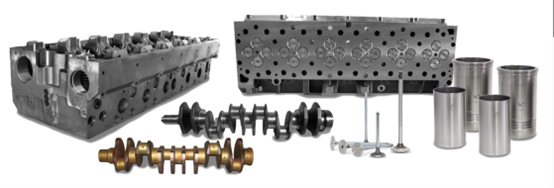
The intake and exhaust valves of a diesel generator are precision components responsible for sealing the combustion chamber and controlling gas exchange during operation. They play a critical role in ensuring the engine’s power, fuel efficiency, reliability, and durability.
Valves operate under extremely harsh conditions. The intake valve temperature can reach 300–400°C, while the exhaust valve temperature can reach 700–900°C. Due to these conditions, the valve working surface is prone to ablation. Since exhaust valves, especially for certain generator brands, are expensive and sometimes difficult to source, understanding their failure timing, causes, and repair methods is essential for extending service life and reducing maintenance costs.
Repair Method for Exhaust Valve Working Surface
Exhaust valves are generally more expensive than intake valves, and some imported models are difficult to obtain. Therefore, mastering repair techniques for the valve working surface is highly valuable.
In practice, the oxyacetylene neutral flame spray welding process has proven effective. For example, using Ni45 alloy powder can minimize deformation after repair. The resulting spray welding layer offers excellent corrosion resistance, wear resistance, heat resistance, and oxidation resistance. This alloy belongs to the Ni-Cr-Si series and contains approximately 10% cobalt.
Preparation for Spray Welding
(1) Thoroughly remove oil stains and carbon deposits from the valve. Inspect the valve to ensure there are no cracks and that the head diameter meets original specifications. Machine the valve face into an arc groove to remove the fatigue and pitted layers, increase surface roughness, and create a suitable cavity for the welding material.
(2) Use an SPH-1/h spray welding torch with oxygen pressure of 40 KPa and acetylene pressure ≥50 KPa. Maintain a valve rotation speed of 1–1.5 r/min.
Spray Welding Process
(1) One-step spray welding: First, preheat the entire valve head to approximately 250°C. Then heat the working surface area while feeding alloy powder intermittently or continuously. Keep the flame 10–20 mm from the surface. When a “mirror reaction” appears at the remelting point, move the spray gun forward until the entire working surface is covered.
(2) After welding, place the valve vertically on an iron plate and allow it to cool naturally to room temperature. Then polish the working surface.
Common Types of Valve Damage
Valve Wear in Diesel Generators
Excessive valve clearance causes repeated impacts between the valve and valve seat during operation, resulting in grooving and widening of the working surface. The exhaust valve is also exposed to high-temperature gases, leading to oxidation, melting, and surface pitting.
The valve stem continuously rubs against the valve guide, increasing clearance and causing vibration, which leads to uneven wear of the valve head. Poor sealing may result in air leakage. Over time, wear also occurs on the tapered surface, stem, and lower face of the valve head.
Burned Valves in Diesel Generators
Valve burning is primarily caused by air leakage due to poor sealing between the valve and valve seat. Contributing factors include improper valve-seat matching, insufficient valve clearance, weak valve spring elasticity, and excessive carbon deposits.
Long-term operation under heavy load beyond design limits accelerates valve wear. It can also deform the cylinder head, valve seat, and valve guide, affecting sealing and heat dissipation, leading to valve ablation.
High engine temperatures may also cause oxidation and decomposition of lubricating oil and fuel, forming deposits on the valve head and stem. These deposits reduce sealing performance and lead to air leakage and valve damage.
Diesel Generator Valve Inspection
(1) During maintenance, check the valve stem tail for bending, wear, or deformation. Inspect the working surface and stem for burnout or damage, and replace if necessary.
(2) Use calipers to measure the valve stem diameter at multiple points. Use a dial indicator to measure deviation at the stem end. If the deviation exceeds allowable limits, replace the valve.
Light Grinding Method for Valve Repair
If the valve cone surface shows wear, grooves, or minor pitting, and the valve head thickness and stem-guide clearance meet requirements, light grinding can be performed.
The principle of light grinding is to minimize material removal while achieving a smooth surface. The valve is ground back and forth without feed until no sparks appear.
(1) Ensure the grinding wheel surface is flat. If uneven, correct it using a diamond dressing tool.
(2) Select an appropriate fixture to securely hold the valve. Adjust the grinding angle according to specifications.
(3) Start the grinding wheel and fixture motor. Perform light grinding using the control handle. If the valve stem end face is uneven, release and reposition the valve.